Contours and Bounding Rectangles
 Figure 1. Sequence of algorithms used for auto-aligning and auto-shooting with the high tower goal.
Once the filters are applied and the target is reasonably isolated (small noise is permissible because it will be filtered out), information about the collection of pixels is extracted. This post will cover the process of turning raw pixel data into something more meaningful.
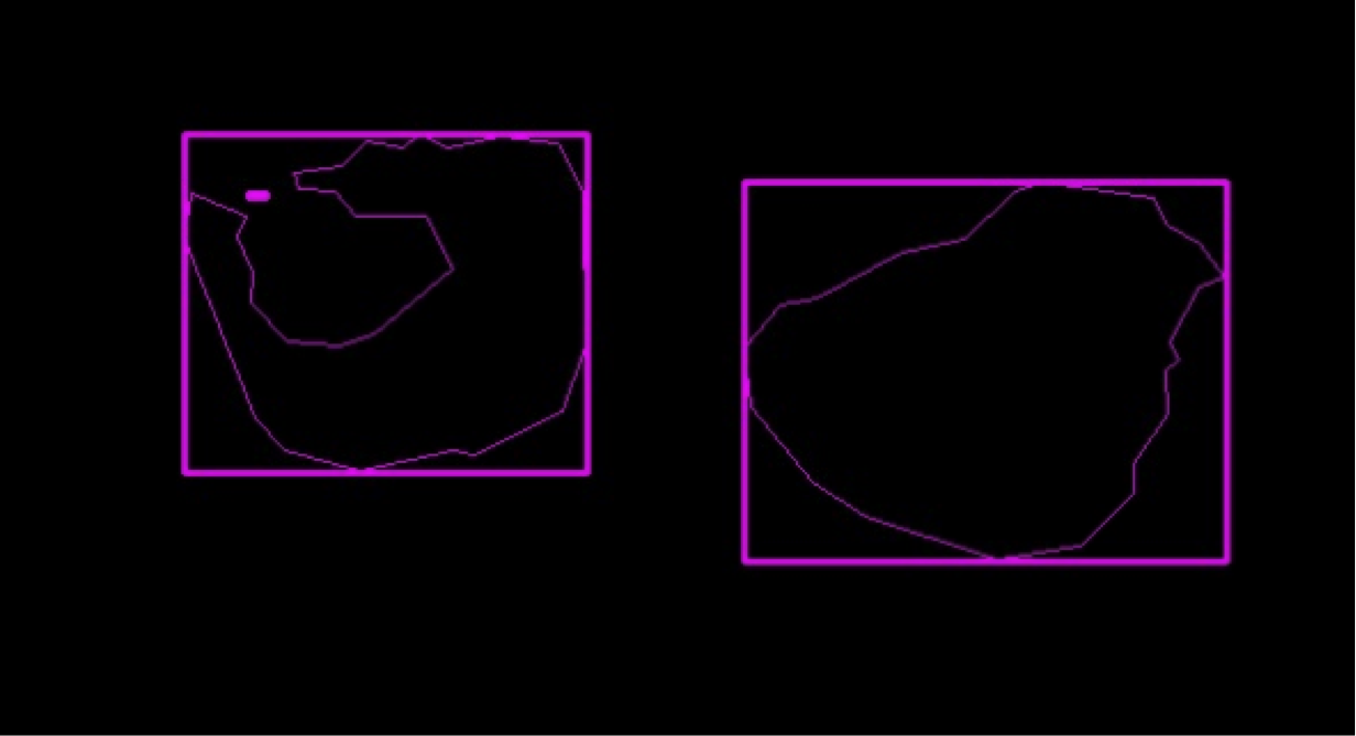 Figure 2. The contours (thin pink) of the shapes are essentially outlines, while the bounding rectangles (thick pink) enclose the contours.
Contours are essentially lines that describe the borders of an object that have the same color or intensity. This was why eliminating noise was a crucial step: every distinct region of color will be listed as a contour, and this cripples performance. The next step is to extract the bounding rectangles from all the contours. Bounding rectangles are the smallest possible rectangles that completely enclose the contour. For our team, we use rotated bounding rectangles because if the camera was ever tilted (ex: robot goes across tilted ramp), nothing about the tower goal will change. Bounding rectangles and contours give information about the width of the object in pixels (which can be used to calculate distance to target), angular rotation, and location relative to the robot.
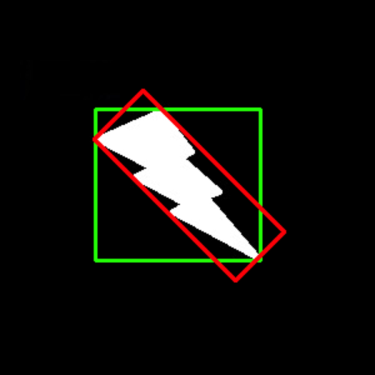 Figure 3. The bounding rectangle (green) will always have the same axes, so for angular robustness, a rotated bounding rectangle (red) will be needed.
Next, a collection of algorithms targeting the angular rotation of the bounded rectangle, ratio of contour area to bounded rectangle area, and ratio of bounded rectangle side lengths are used. A key algorithm that eliminated a large chunk of noise was by using the fact that the center of mass of the U-shaped tape is outside of the contour area of the tape.
I’ll get to writing another post describing the use of this data to empower the robot, but it may take a while, so here’s a brief summary:
Once the tape surrounding the high tower goal has been isolated, different measurements including distance, yaw, and pitch can be extracted by using trigonometric ratios. This data is then used to turn the robot and angle the shooter.